


Calculating Series Resistance: A Complete Expert Guide
This article explains how to calculate series resistance in electrical circuits, why it matters for performance and safety, and how engineers use it to design reliable systems.
Table of Contents
- What Is Series Resistance?
- How Series Resistance Is Calculated
- Why Series Resistance Matters
- Engineering Applications
- Common Mistakes When Calculating Series Resistance
- Advanced Considerations
- Top 5 Frequently Asked Questions
- Final Thoughts
- Resources
What Is Series Resistance?
Series resistance refers to the total opposition to current flow when resistors are connected end-to-end in a single electrical path. In a series circuit, the same current flows through every component because there is only one available route for electrons to travel. This creates a cumulative resistance value that directly affects current, voltage distribution, power consumption, and overall circuit behavior.
Engineers rely on series resistance calculations when designing devices ranging from LED lighting arrays and sensor networks to heating elements and circuit protection systems. Even slight miscalculations can cause excessive voltage drops, overheating, or inefficient power delivery.
How Series Resistance Is Calculated
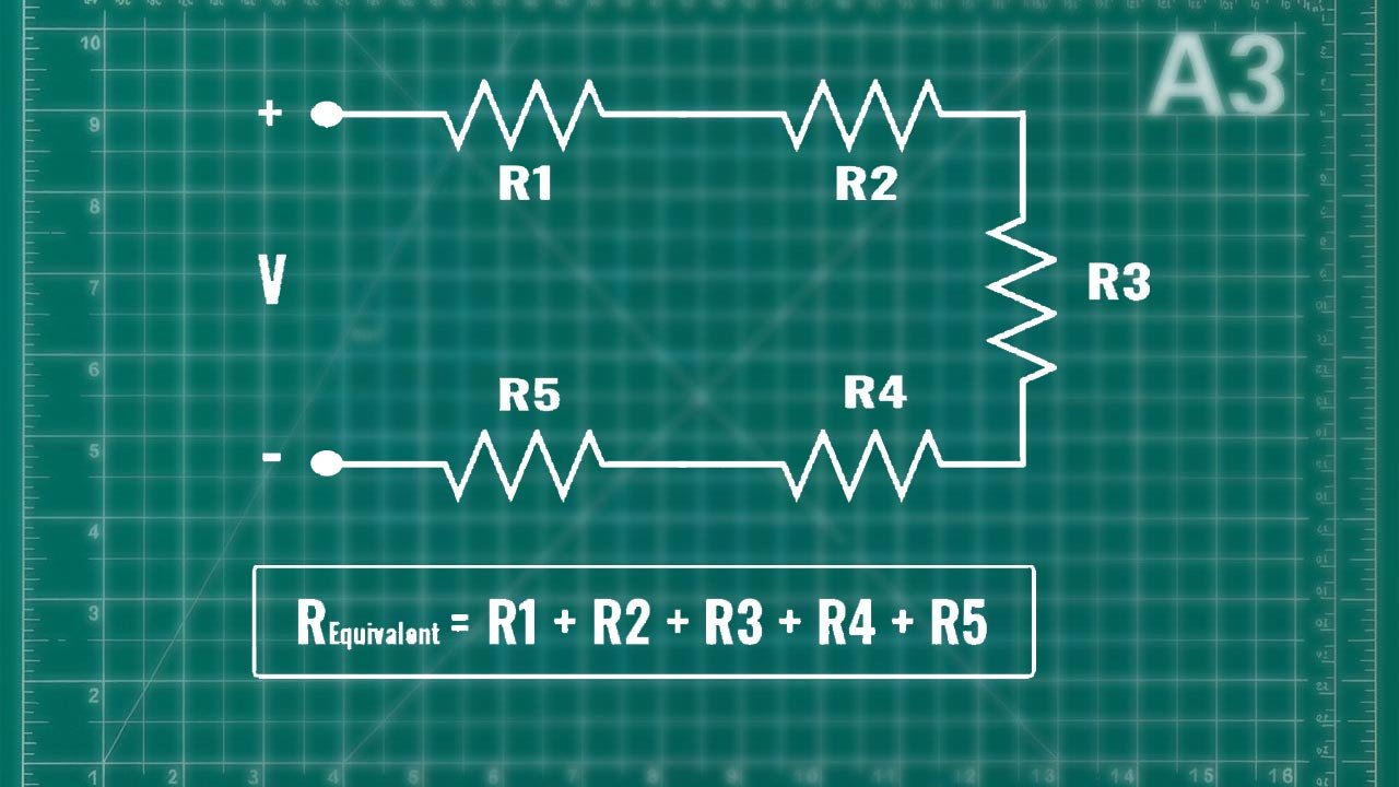
The formula for calculating the total resistance in a series circuit is extremely straightforward:
R_total = R1 + R2 + R3 + … + Rn
This linear addition works because the resistances simply stack along the same current path.
In real-world engineering contexts, however, several deeper considerations arise:
- Tolerance values, which indicate how much a resistor may vary from its rated resistance.
- Temperature coefficients (TCR), which cause resistance to increase or decrease depending on heat levels.
- Material properties, where carbon film, metal oxide, and wire-wound resistors respond differently under load.
- Parasitic resistance from wires, connectors, and solder traces that can add measurable resistance in precision systems.
For most standard circuits, adding resistor values is enough. But in high-accuracy or high-power applications, engineers often measure the actual resistance using precision digital multimeters (DMMs) or four-wire Kelvin measurement techniques to remove lead-resistance error.
Why Series Resistance Matters
Understanding and correctly calculating series resistance is essential for three major engineering reasons:
1. Voltage Distribution
In a series circuit, voltage divides across resistors proportional to their resistance values. Incorrect calculations can lead to improper voltage levels at downstream components. This is particularly important in:
- Sensing applications where voltage accuracy impacts data integrity
- LED arrays where uneven voltage drops cause brightness inconsistencies
- Analog measurement circuits where signals are extremely sensitive
2. Current Limiting
Series resistors are frequently used to limit current for safety and device protection. For example:
- Microcontroller pins typically require current-limiting resistors to protect against overcurrent conditions
- LEDs must be paired with an appropriate series resistor to prevent burnout
- Battery circuits often include series resistance to reduce short-circuit risk
Incorrect values can lead to overheating, component failure, or unpredictable operational behavior.
3. Power Dissipation
Every resistor in a series circuit dissipates heat according to P = I²R. Engineers must evaluate:
- Power ratings
- Thermal performance
- Ambient temperature effects
- Safety margins
Overlooking total power dissipation is one of the most common causes of premature circuit failure.
Engineering Applications
Series resistance plays a critical role across numerous innovation and technology management scenarios.
Product Development and Optimization
Design teams use series resistors during prototyping to:
- Control current in developmental circuits
- Test voltage responses under varying load conditions
- Establish safe operating regions for new hardware
Energy Efficiency in System Design
Efficiency-focused industries monitor series resistance to minimize energy loss, especially in:
- Battery-powered IoT sensors
- Wearable technologies
- Low-voltage embedded systems
Even small improvements can translate to longer battery life and enhanced sustainability.
Failure Prevention and Reliability Engineering
Excessive series resistance from aging components, corroded connectors, or degraded materials can produce:
- Voltage instability
- Unexpected current drops
- Thermal failures
Reliability engineers often evaluate total circuit resistance when diagnosing system issues or forecasting long-term performance.
Common Mistakes When Calculating Series Resistance
Even though the math is simple, several technical mistakes often lead to incorrect calculations:
1. Ignoring Tolerance
Many resistors include ±1%, ±5%, or ±10% tolerances. In large series strings, worst-case tolerance stacking can produce significant deviations from expected values.
2. Overlooking Temperature Effects
Resistors heat up under load. Metal film resistors have lower temperature coefficients than carbon film resistors, and wire-wound resistors can vary significantly at high temperatures.
3. Forgetting Parasitics
PCB traces typically add 0.01 to 0.1 ohms depending on length and width. Although negligible in most circuits, precision systems cannot ignore this.
4. Incorrect Power Rating
If a resistor in a series chain overheats, it may drift in value or fail entirely. Engineers must select proper power ratings with safety margins.
5. Misinterpreting Series vs Parallel
Beginners often confuse series and parallel resistor configurations. Series circuits add resistance; parallel circuits reduce it.
Advanced Considerations
For innovation-driven engineering environments, calculating series resistance may involve deeper system-level thinking.
Dynamic Resistance
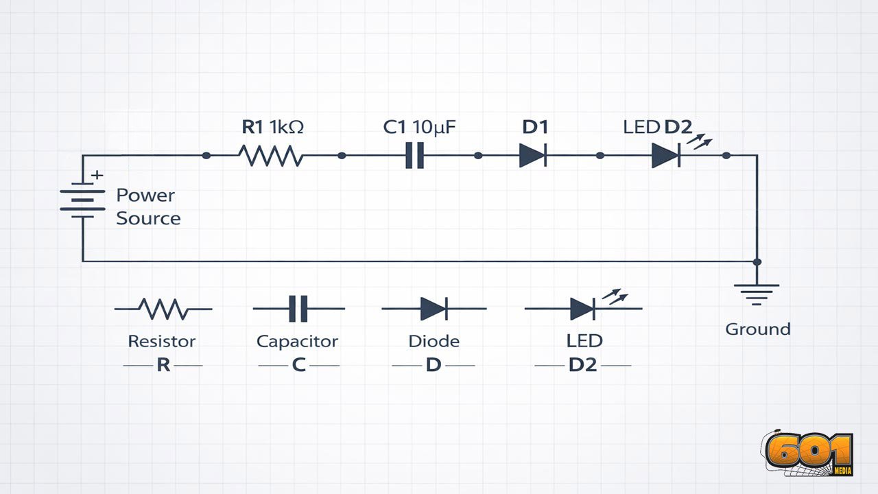
Semiconductor components such as diodes, MOSFETs, and LEDs exhibit dynamic resistance, meaning their effective resistance changes with current. When included in a series chain, these nonlinear behaviors must be modeled using I-V curves.
Frequency-Dependent Effects
At high frequencies, resistors exhibit:
- Inductive reactance
- Parasitic capacitance
- Skin-effect–related resistance increases
RF engineers often perform impedance analysis rather than simple DC resistance calculations.
Smart Circuit Design
Modern systems leverage digital twins and simulation tools such as SPICE to model how resistance changes with load, temperature, and environmental variation. This reduces risk during product development and ensures higher performance consistency.
Top 5 Frequently Asked Questions
Final Thoughts
The most important takeaway is that calculating series resistance is not just simple addition—it’s a foundational part of engineering decision-making. Accurate series resistance values influence voltage levels, thermal behavior, reliability, and energy efficiency. Whether designing LEDs, embedded electronics, or advanced sensor networks, understanding how resistors behave in series enables better performance and safer, more predictable circuit outcomes.


Leave A Comment