


How Batteries Work: Charge Separation, Electron Flow, and Chemical Energy
A practical deep-dive into how batteries really work at the physics and chemistry level, written for hobbyist and student electrical engineers who want to go beyond “volts and amps” and understand what’s happening inside the cell.
Table of Contents
- How Batteries Store Energy: The Big Picture
- Inside a Battery: Core Components and Structure
- Charge Separation: The Heart of a Battery
- Electron Flow and the External Circuit
- Voltage, Current, and Energy in Batteries
- Primary vs. Rechargeable Batteries
- Real-World Effects in Battery Behavior
- Design Tips for Hobbyists and Students
- Top 5 Frequently Asked Questions
- Final Thoughts: Key Takeaways
- Resources
How Batteries Store Energy: The Big Picture
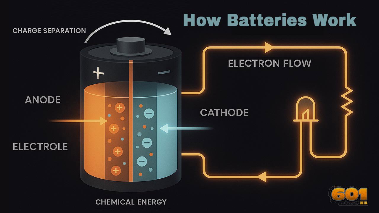
If you strip away the casing, labels, and marketing, a battery is simply a device that converts stored chemical energy into electrical energy through controlled redox (reduction–oxidation) reactions. The key idea is this:
- Chemical reactions create a separation of charge between two electrodes.
- This separation produces an electric potential difference (voltage).
- When you connect a circuit, electrons flow through the external path, doing useful work on the way.
Inside the battery, ions move through an electrolyte between electrodes, while electrons are forced to move through your circuit. The battery acts like a chemical “pump” that pushes electrons from one terminal to the other, as long as the underlying chemistry can support the redox reactions.
To understand batteries well enough to design and debug circuits, you need to understand three pillars:
- Charge separation: how the chemistry creates a voltage.
- Electron flow: how and why current flows in the external circuit.
- Chemical energy: how reactions store and release energy over time.
Inside a Battery: Core Components and Structure
Every battery, from a coin cell to a large EV pack, is built from the same fundamental elements:
- Anode (negative electrode in discharge mode)
- Cathode (positive electrode in discharge mode)
- Electrolyte (ionic conductor, electronic insulator)
- Separator (prevents short, allows ion flow)
- Current collectors and terminals
Anode
The anode is the electrode where oxidation occurs during discharge. Oxidation means it loses electrons. Those electrons cannot travel through the electrolyte, so they are pushed into the external circuit.
- In alkaline cells, the anode is typically zinc.
- In lithium-ion cells, the anode is usually graphite with intercalated lithium.
Cathode
The cathode is where reduction happens during discharge. Reduction means it gains electrons arriving from the external circuit.
- In alkaline cells, the cathode often uses manganese dioxide.
- In lithium-ion cells, it could be a compound like LiCoO₂, NMC, or LFP.
Electrolyte
The electrolyte allows ions to move between electrodes, completing the internal circuit. It does not allow electrons to pass.
- In alkaline batteries, it is usually potassium hydroxide (KOH) solution.
- In lithium-ion batteries, it is a lithium salt dissolved in an organic solvent or embedded in a polymer or ceramic matrix.
This separation of ionic and electronic conduction is essential. It forces electrons to move through your circuit instead of just recombining internally.
Separator
The separator is a porous, electrically insulating membrane that prevents direct contact between anode and cathode while allowing ions in the electrolyte to pass. Without it, the cell would short internally and rapidly discharge or fail dangerously.
Current Collectors and Terminals
The electrodes themselves are often coated on metal foils (like copper or aluminum) called current collectors. These connect to the external terminals you see as the + and – on a battery. They provide low-resistance paths for electrons into and out of the cell.
Charge Separation: The Heart of a Battery
At the core of battery operation is charge separation. A battery creates a voltage by arranging materials so that one electrode “wants” to give up electrons more strongly than the other.
Electrode Potentials and Redox Pairs
Every electrode material has a characteristic tendency to lose or gain electrons, described by its electrochemical potential. When you pair two different materials with an electrolyte, you set up:
- An anode that has a high tendency to oxidize (release electrons).
- A cathode that has a higher tendency to be reduced (accept electrons).
The difference in these tendencies forms the open-circuit voltage (OCV) of the cell. For example:
- Alkaline AA cell: about 1.5 V
- Li-ion cell: about 3.6–3.7 V nominal
What Actually Separates the Charge?
Consider a fresh cell not connected to a circuit. At the microscopic level:
- Atoms at the anode give up electrons and become positively charged ions.
- These ions migrate into the electrolyte.
- The electrons they lost cannot follow through the electrolyte, so they accumulate on the anode side, making it negatively charged.
- Meanwhile, at the cathode side, the lack of electrons (relative to the redox pair) makes it effectively more positive.
This builds an electric field between the electrodes. As the separation grows, the electric field opposes further charge transfer. Eventually, an equilibrium is reached where the chemical driving force is balanced by the electric field, and the cell sits at its open-circuit voltage.
Potential Energy of Separated Charge
You can think of the separated charges as stored potential energy, just like water stored at a height in a reservoir. The voltage is analogous to height, and the charge is analogous to the volume of water. When you give the charges a path (a circuit), they “roll downhill” and deliver energy.
Electron Flow and the External Circuit
Once you connect a load between the battery terminals, the system is no longer in equilibrium.
Direction of Electron Flow
During discharge:
- Electrons flow from the anode (negative terminal) to the cathode (positive terminal) through the external circuit.
- Conventional current (by definition) flows from positive to negative, opposite to electron flow.
Coupling of Internal and External Paths
For every electron that leaves the anode into the external circuit, an ion-based counterpart moves inside the cell:
- At the anode, oxidation produces positive ions and releases electrons.
- Ions drift through the electrolyte toward the cathode.
- At the cathode, reduction consumes electrons arriving from your circuit and ions arriving through the electrolyte.
This keeps the cell electrically neutral overall while supporting continuous current.
Why the Electrolyte Must Not Conduct Electrons
If electrons could freely flow through the electrolyte, they would bypass your load and recombine internally, wasting the stored energy as heat and killing the cell. The electrolyte’s role is to:
- Conduct ions efficiently.
- Block electrons completely.
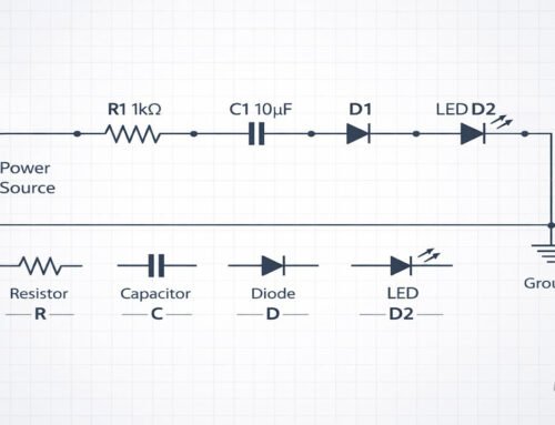
That is what forces the electrons through your circuit, where they can drive logic, motors, LEDs, and more.
Voltage, Current, and Energy in Batteries
A lot of confusion for beginners comes from mixing up voltage, current, capacity, and energy. For a battery-powered design, you should clearly distinguish them.
Voltage (V)
Voltage is the potential difference created by charge separation. It is mainly set by chemistry:
- An alkaline cell is about 1.5 V whether it is AA, C, or D size.
- A lithium-ion cell is about 3.6–3.7 V nominal across many form factors.
Cell size does not change the voltage; it changes how much charge and energy are available.
Current (I)
Current is the rate at which charge flows, measured in amperes (A). The maximum practical current a battery can supply is limited by:
- Internal resistance (ohms).
- Electrode surface area and kinetics.
- Heat dissipation and safety constraints.
A small coin cell may be rated for tens of milliamps, while a high-rate lithium-ion cell might handle tens of amps.
Capacity (Ah or mAh)
Capacity measures how much charge the battery can theoretically deliver from a full charge down to its cutoff point:
- Q = I × t
- Example: a 2000 mAh cell can ideally supply 200 mA for about 10 hours.
In reality, capacity depends on discharge rate, temperature, and aging.
Energy (Wh)
Energy combines voltage and capacity:
- Energy (Wh) ≈ Voltage (V) × Capacity (Ah)
- For example, a 3.7 V, 2 Ah Li-ion cell stores about 7.4 Wh.
This is the real measure of “how much work” the battery can do, such as how long it can power a certain load.
Internal Resistance and Voltage Drop
No real battery is ideal. Each has an internal resistance, often modeled as a small resistor in series with an ideal voltage source.
- When current flows, V_load = V_ocv − I × R_internal.
- Higher current draws cause more voltage sag at the terminals.
For hobby projects, this explains why:
- Motors may stall when powered by weak or nearly empty cells.
- Microcontrollers brown out under inrush or peak loads.
Primary vs. Rechargeable Batteries
The chemistry that drives charge separation also determines whether a battery is single-use (primary) or rechargeable (secondary).
Primary Cells
Primary cells are designed for one-way chemical reactions:
- Once the reactants are consumed and products formed, you cannot practically drive the reaction backward.
- Examples: alkaline, zinc-carbon, most coin cells.
Attempting to recharge primary cells can be dangerous and is not recommended.
Rechargeable (Secondary) Cells
Rechargeable cells use chemistries that are reversible within safe operating limits:
- During discharge: chemical energy converts to electrical energy, as usual.
- During charge: an external power source forces current in the opposite direction, driving the chemical reaction backward and restoring the original, higher-energy state.
Examples include:
- Lithium-ion and lithium-polymer cells.
- Nickel-metal hydride (NiMH).
- Lead–acid batteries.
Charge Separation in Reverse
When charging, you are essentially:
- Using energy from a charger to re-separate charge and rebuild the chemical potential difference.
- Moving ions and electrons back to their high-energy positions.
That is why proper charge control is critical. Overcharging can push the chemistry beyond its safe limits, leading to gas formation, plating, or thermal runaway.
Real-World Effects in Battery Behavior
In theoretical diagrams, batteries look simple. In real circuits, they show quirks that matter to hobbyists and students.
State of Charge (SoC)
State of charge represents how full the battery is, often expressed as a percentage. It is linked to:
- How much of the active material has reacted.
- The current balance of reactants and products at each electrode.
Many chemistries exhibit a roughly flat voltage plateau over a wide SoC range, then drop sharply near empty (for example, many lithium-ion systems). This makes SoC estimation non-trivial; you may need:
- Open-circuit voltage measurements after rest.
- Coulomb counting (integrating current over time).
Temperature Effects
Temperature changes reaction rates, internal resistance, and diffusion processes:
- Cold: higher internal resistance, slower kinetics, reduced usable capacity.
- Hot: lower resistance, but accelerated aging and safety risks.
For hobby projects with Li-ion cells, operating near room temperature and avoiding extremes dramatically improves lifespan.
Self-Discharge
Even when not connected, batteries slowly lose charge due to side reactions and leakage paths:
- NiMH and NiCd typically have higher self-discharge than Li-ion.
- Modern “low self-discharge” NiMH cells (often pre-charged out of the box) are optimized to minimize this effect.
Cycle Life and Degradation
Every charge–discharge cycle causes small structural and chemical changes:
- Electrodes may crack or grow passivation layers.
- Electrolyte may decompose slowly.
- Active lithium or other ions may become trapped and unavailable.
Over time, this reduces capacity and increases internal resistance. For students, this shows up as older cells that:
- Drop voltage faster under load.
- Appear to “charge quickly” but deliver less runtime.
Design Tips for Hobbyists and Students
Understanding charge separation and electron flow gives you practical tools for better battery-powered designs.
Match Chemistry to Use Case
- Low-current, long-life devices (sensors, remotes): alkaline or lithium primary cells can be ideal.
- High-current, rechargeable applications (robots, drones, portable tools): lithium-ion or LiPo packs are often preferred.
- Rugged, inexpensive backup (small UPS, automotive): lead–acid still dominates.
Respect Voltage Limits
For each chemistry:
- Know the nominal voltage and allowable minimum and maximum.
- For Li-ion cells, never discharge below the recommended cutoff (often around 2.5–3.0 V per cell) and never exceed the maximum charge voltage (often 4.2 V per cell for standard chemistries).
Use proper protection circuits (battery management systems, BMS) when working with multi-cell packs.
Design with Internal Resistance in Mind
- Estimate the worst-case current draw of your circuit.
- Check the cell’s datasheet for internal resistance and max discharge current.
- Allow margin so voltage sag under peak load does not cause brownouts.
This is especially important for:
- Motors, servos, and high-power LEDs.
- RF modules with high transmit bursts.
Series vs. Parallel Cell Connections
- Series connection increases voltage; capacity (Ah) stays the same.
- Parallel connection increases capacity (Ah); voltage stays the same.
Always use cells of the same type, age, and state of charge in a pack. Imbalanced cells can lead to overcharge or over-discharge in series strings.
Safety Practices
- Never short battery terminals.
- Use appropriate fuses or polyfuses in high-current systems.
- Do not charge cells with improvised circuits; use chargers designed for the specific chemistry.
- Ensure proper ventilation and mechanical protection for packs.
For lithium-based cells, treat them with the same respect you would give to any high-energy component: they are safe when used correctly but unforgiving if abused.
Top 5 Frequently Asked Questions
Final Thoughts: Key Takeaways
The most important thing to remember about batteries is that they are engineered systems for controlled charge separation and recombination. The chemistry inside sets:
- How much voltage you get (electrode potentials).
- How much current you can safely draw (internal resistance and kinetics).
- How much total work the battery can do (stored chemical energy, expressed as Wh).
As a hobbyist or student electrical engineer, treating a battery as “just a 3.7 V source” is leaving a lot of power on the table. When you understand:
- How ions and electrons move in complementary paths.
- How internal resistance and temperature shape real-world behavior.
- How chemistry controls reversibility, safety, and lifetime.
you can design circuits that are more reliable, safer, and better optimized for your use case.
This knowledge is not just academic. It informs your choice of cell types, pack configurations, protection circuits, and even enclosure design. Whether you are building a simple sensor node or a high-power robot, understanding charge separation, electron flow, and chemical energy gives you the mental model you need to predict battery behavior instead of being surprised by it.
Resources
- “Basic Battery Theory” – Battery University
- “Fundamentals of Electrochemistry” – text and lecture notes from various university electrochemistry courses
- Manufacturers’ datasheets for alkaline, NiMH, Li-ion, and LiPo cells
- IEEE and IEC documents on battery safety and testing standards
Leave A Comment