


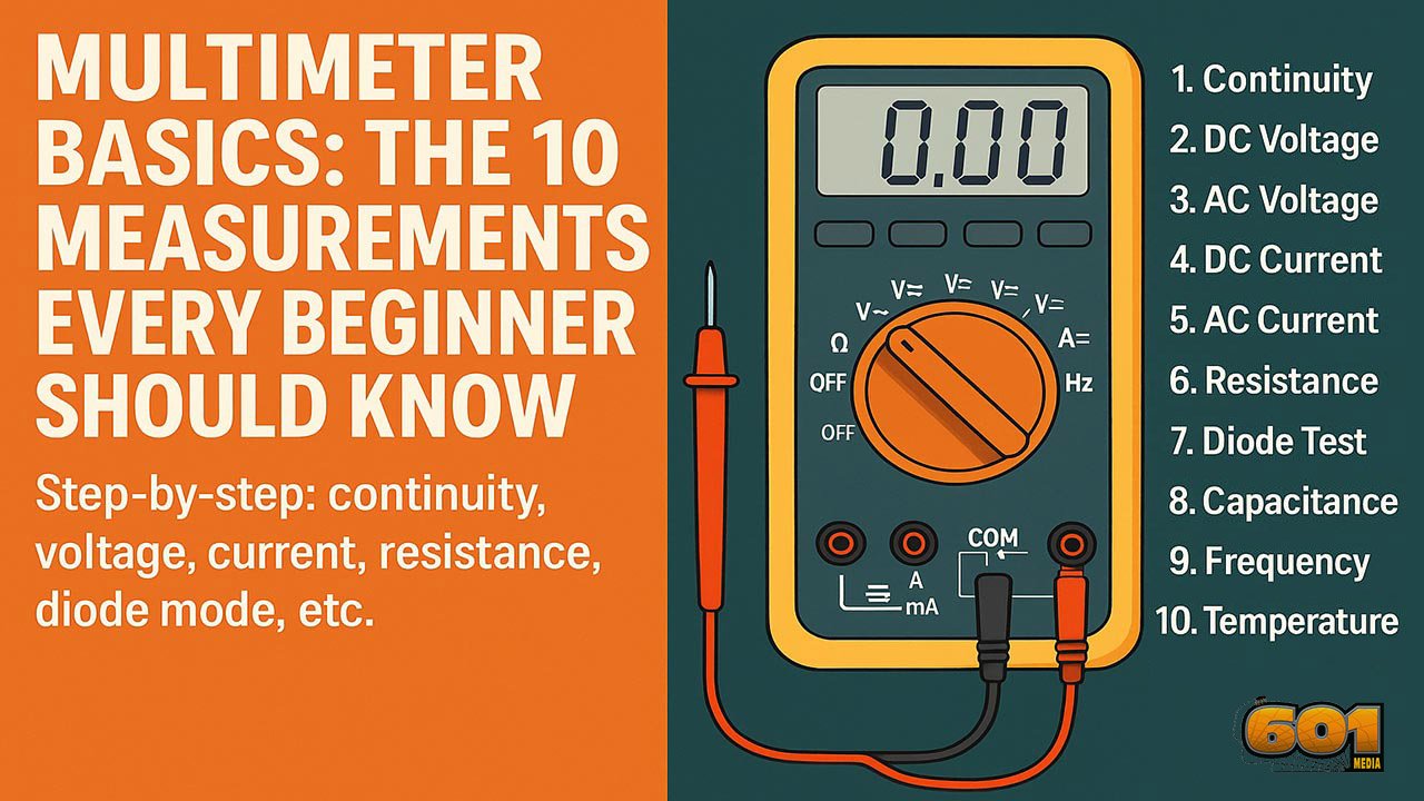
Multimeter Basics: The 10 Measurements Every Beginner Should Know
Learn the ten multimeter functions that unlock 90% of beginner troubleshooting—plus clear, step-by-step instructions for continuity, voltage, current, resistance, diode mode, and more.
Table of Contents
- Introduction
- Why Every Beginner Needs a Multimeter
- Understanding Your Multimeter
- The 10 Essential Measurements
- Safety Guidelines
- Top 5 Frequently Asked Questions
- Final Thoughts
- Resources
Introduction
A digital multimeter (DMM) is the single most useful tool for learning electronics, diagnosing automotive faults, or checking basic home electrical issues. It turns invisible electrical behavior into numbers you can act on. The trick is knowing which mode to choose, where to plug the leads, and how to connect the meter to the circuit without damaging anything.
This beginner guide focuses on the ten measurements that cover most real-world troubleshooting. You’ll learn what each mode is for, how to do it step-by-step, what “normal” readings look like, and the common mistakes that trip people up.
Why Every Beginner Needs a Multimeter
A multimeter helps you answer the questions that matter in minutes:
- Is there power here?
- Is this wire broken or connected?
- Is this component likely good or obviously bad?
- Is this circuit drawing too much current?
Without measurements, troubleshooting becomes guesswork. With measurements, you isolate the problem systematically: verify power, verify the path, verify the load, then verify the control signal. That simple flow saves hours and prevents part-swapping.
Understanding Your Multimeter
Ports
Most beginner DMMs have three common ports:
- COM (black lead): the reference point for almost every measurement
- V/Ω (red lead): voltage, resistance, continuity, diode, frequency, capacitance (varies by model)
- mA/10A (red lead): current measurements (often split into a fused mA port and a higher-current 10A port)
Rule of thumb: if you’re measuring voltage, resistance, continuity, or diodes, the red lead is almost always in the V/Ω port. Only move the red lead to a current port when you intentionally measure current.
Dial and Symbols
The rotary selector chooses the measurement type. Common symbols:
- V⎓ or V—: DC voltage
- V~: AC voltage
- A⎓ or A—: DC current
- A~: AC current
- Ω: resistance
- 🔔 or sound-wave icon: continuity
- →|: diode test
- Hz: frequency
- F: capacitance
- °C/°F: temperature (with a probe)
Display and Units
Your screen may show:
- Units: V, A, Ω, Hz, F, °C/°F
- Prefixes: m (milli), k (kilo), M (mega), µ (micro)
- OL: overload or open loop, meaning “out of range” or “not connected” depending on mode
The 10 Essential Measurements
1) Continuity (Step-by-step)
Continuity mode checks whether two points are electrically connected with low resistance. Many meters beep when the resistance is below a threshold (often 30–50 Ω, varies by model).
- Best for: wires, fuses, switches, connectors, solder joints, PCB traces
Steps:
- Turn the dial to continuity (beep icon). If continuity shares a dial position with diode mode, press the function/select button until the beep icon appears.
- Plug black lead into COM and red lead into V/Ω.
- Touch the probes together to confirm you get a beep (sanity check).
- Touch one probe to each end of the wire, fuse, or connection you want to test.
- Beep or very low resistance reading usually means connected; no beep and OL typically means open (broken path).
Common mistakes: testing on a powered circuit; touching insulation instead of metal; assuming “no beep” always means “bad” when some meters have higher thresholds.
2) DC Voltage (Step-by-step)
DC voltage is the foundation of electronics: batteries, USB power, most embedded systems, and vehicle electrical systems are DC.
- Best for: batteries, power rails, adapters, sensors, control boards
Steps:
- Set the dial to DC voltage (V⎓ or V—).
- Black lead to COM, red lead to V/Ω.
- Measure in parallel: place the black probe on ground/negative and red probe on the point you want to check.
- Read the display. A negative sign means your probes are reversed (safe and common).
Quick reference readings:
- AA alkaline: about 1.5 V new, lower as it drains
- USB: around 5 V
- Common logic rails: 3.3 V and 5 V
3) AC Voltage (Step-by-step)
AC voltage is used for household power and many appliances.
- Best for: outlets, appliance power, transformers (primary side)
Steps:
- Set the dial to AC voltage (V~).
- Black lead to COM, red lead to V/Ω.
- Probe in parallel across the source. For outlets, insert probes carefully into the hot and neutral slots following local safety practice.
- Read the display.
Safety note: mains voltage can injure or kill. If you’re unsure, do not probe live mains.
4) DC Current (Step-by-step)
Current measurement is where beginners blow fuses, because the meter must be inserted in series and effectively becomes part of the circuit.
- Best for: checking device draw, parasitic drain, troubleshooting “it keeps blowing fuses” issues
Steps:
- Power off the circuit.
- Move the red lead to the correct current port: start with the 10A port if you have no idea how much current to expect.
- Set the dial to DC current (A⎓ or A—). If your meter supports mA and A ranges, start high.
- Break the circuit path and insert the meter in series: the circuit current must flow through the meter.
- Power on and read. If the reading is low, you can move to a more sensitive mA range (after powering off and moving the lead).
Common mistakes: measuring current like voltage (in parallel), leaving the lead in the current port then measuring voltage, exceeding the current rating of the port.
5) AC Current (Step-by-step)
AC current measurement depends on the meter. Some require a clamp accessory; others allow in-series measurement on a dedicated range.
- Best for: checking appliance draw, verifying load behavior (when supported)
Steps (in-series method, if your meter supports it):
- Power off the circuit.
- Move red lead to the correct current port (often 10A for safety).
- Select AC current (A~).
- Insert meter in series with the load.
- Power on and read.
Tip: if you’ll measure AC current often, a clamp meter is usually safer and easier.
6) Resistance (Step-by-step)
Resistance mode measures how strongly a component resists current flow.
- Best for: resistors, checking suspected broken paths (with power off), verifying sensor resistance behavior
Steps:
- Power off the circuit and, if possible, isolate the component (lift one leg) for accurate readings.
- Set the dial to Ω.
- Black lead to COM, red lead to V/Ω.
- Probe across the component leads and read the value.
Common mistakes: measuring resistance on a powered circuit; reading resistance in-circuit where parallel paths change the result.
7) Diode Test (Step-by-step)
Diode mode applies a small test current and displays forward voltage drop. It’s the quickest way to check diodes and many semiconductor junctions.
- Best for: rectifier diodes, LEDs (often), quick checks on transistors (with caveats)
Steps:
- Set the dial to diode mode (→|). If diode shares a dial position with continuity, use the function/select button to switch modes.
- Black lead to COM, red lead to V/Ω.
- Touch red probe to the anode and black probe to the cathode (stripe side for many diodes).
- Read forward voltage. Silicon diodes often read roughly 0.55–0.75 V; Schottky diodes often read lower.
- Reverse the probes. A healthy diode typically shows OL or a very high value in reverse direction.
Common mistakes: trying to test diodes while they are still in a complex circuit; confusing polarity markings.
8) Capacitance (Step-by-step)
Capacitance mode estimates capacitor value. Accuracy varies by meter and capacitor type.
- Best for: quick checks of electrolytics and film capacitors, verifying “wrong part installed” issues
Steps:
- Disconnect power and safely discharge the capacitor.
- Set dial to capacitance (F).
- Black lead to COM, red lead to V/Ω or the capacitance port (varies by meter).
- Probe across the capacitor leads and wait for the reading to settle.
Tip: capacitance value alone does not catch every failure mode; ESR (equivalent series resistance) can be the real culprit.
9) Frequency (Step-by-step)
Frequency measurement tells you how often a waveform repeats, measured in hertz (Hz).
- Best for: mains frequency checks, PWM signals, basic function generator validation
Steps:
- Set the dial to Hz (or press the function/select button to enable Hz on the shared position).
- Black lead to COM, red lead to V/Ω.
- Probe the signal in parallel (ground to reference, red to signal point).
- Read the frequency.
10) Temperature (Step-by-step)
Some meters support a thermocouple probe for temperature.
- Best for: checking heatsinks, ambient temperature, electronics hot spots
Steps:
- Plug the thermocouple into the correct ports (often labeled for temperature).
- Select °C or °F mode.
- Place the probe tip on the target surface or in airflow.
- Read the temperature once stable.
Safety Guidelines
- Use the correct port: voltage and resistance use V/Ω; current uses mA/10A.
- Start on the highest current range if you’re unsure, then step down.
- Never measure resistance or continuity on a powered circuit.
- For mains work, use a meter rated for the environment (CAT rating) and inspect leads for damage.
- Keep fingers behind the probe guards to reduce slip risk.
Top 5 Frequently Asked Questions
Final Thoughts
If you can confidently measure continuity, DC voltage, AC voltage, current, resistance, and diode behavior, you can diagnose most beginner-level electrical problems quickly and safely. The most important habit is choosing the correct port and connecting method: voltage is measured in parallel, current is measured in series, and resistance/continuity should be measured with power off. Once those rules become automatic, your multimeter stops being intimidating and starts feeling like a superpower.


Leave A Comment