


Circuit Diagrams for Beginners: How to Read and Draw Schematics
Understanding circuit diagrams is the foundation of electronics, electrical engineering, and modern product development. Whether you are a student, maker, or early-stage innovator, learning how to read and draw schematics turns abstract theory into practical, buildable systems.
Table of Contents
- What Is a Circuit Diagram?
- Why Schematics Matter in Technology Innovation
- Common Schematic Symbols Explained
- How to Read Circuit Diagrams Step by Step
- How to Draw Your Own Circuit Diagrams
- Best Practices for Clear Schematics
- Common Beginner Mistakes
- Tools and Software for Drawing Schematics
- Top 5 Frequently Asked Questions
- Final Thoughts
- Resources
What Is a Circuit Diagram?
A circuit diagram, also called a schematic, is a symbolic representation of an electrical circuit. Instead of showing physical layouts, it uses standardized symbols to describe how components are electrically connected. This abstraction allows engineers to focus on function rather than form. In innovation management, schematics act as the shared language between ideation, prototyping, and manufacturing. According to engineering workflow studies, design errors caught at the schematic stage can reduce downstream production costs by over 60 percent.
Why Schematics Matter in Technology Innovation
Schematics are not just technical drawings; they are decision-making tools. In product development, they enable rapid iteration, peer review, and cross-functional collaboration. Hardware startups that standardize schematic documentation early tend to reach functional prototypes faster. This aligns with lean innovation principles, where clarity reduces waste and accelerates learning cycles. Schematics also support regulatory compliance, safety reviews, and intellectual property filings. Patent examiners and certification bodies rely heavily on clear circuit representations.
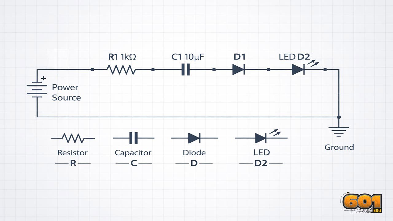
Common Schematic Symbols Explained
Schematics rely on internationally recognized symbols governed by standards organizations such as the Institute of Electrical and Electronics Engineers (IEEE) and the International Electrotechnical Commission (IEC). Resistors are represented as zigzag or rectangular symbols depending on region. Capacitors appear as parallel plates, with polarity indicated for electrolytic types. Diodes use a triangle and line to show current direction, while LEDs add outward arrows to indicate light emission. Power sources are shown as long and short lines for batteries or specialized symbols for AC supplies. Ground symbols define the reference point for voltage measurements, a critical concept for beginners.
How to Read Circuit Diagrams Step by Step
Start by identifying the power source. Locate where voltage enters the circuit and where ground is defined. Next, trace the signal path from input to output, following wires and junctions. Components are typically arranged left to right or top to bottom to reflect signal flow. This is a convention, not a rule, but it improves readability. Pay close attention to labels and reference designators such as R1, C2, or U3. These identifiers link schematic symbols to bills of materials and physical components.
How to Draw Your Own Circuit Diagrams
Begin by listing all required components and their electrical relationships. Translate each component into its schematic symbol and place them logically on the page. Connect components using straight lines to represent wires. Avoid unnecessary crossings. Where connections intersect, use dots to indicate electrical junctions. Label all components with values and reference designators. A schematic without labels is incomplete and difficult to validate or manufacture.
Best Practices for Clear Schematics
Consistency is critical. Use the same symbol style, naming convention, and orientation throughout the diagram. Group related components into functional blocks such as power regulation, signal processing, or control logic. This mirrors systems engineering principles and improves cognitive load management. Leave sufficient spacing between symbols. Overcrowded schematics increase error rates during review and assembly.
Common Beginner Mistakes
One frequent error is confusing physical layout with schematic layout. Schematics do not show where parts sit on a board. Another issue is missing ground references. Floating circuits are one of the most common causes of non-functional prototypes. Beginners also tend to omit component values. Without resistance, capacitance, or voltage ratings, a schematic cannot be validated.
Tools and Software for Drawing Schematics
Modern schematic capture tools range from beginner-friendly to enterprise-grade. Popular options include KiCad, EasyEDA, and Altium Designer.
From an innovation management perspective, open-source tools reduce cost barriers and encourage experimentation, while professional suites integrate seamlessly with manufacturing workflows.
Top 5 Frequently Asked Questions
Final Thoughts
Learning to read and draw circuit diagrams is a leverage skill. It transforms electronics from trial-and-error tinkering into systematic problem solving. For innovators, schematics bridge creativity and execution, enabling scalable, repeatable, and defensible technology development. Mastery at the beginner level sets the stage for advanced design, collaboration, and long-term technical leadership.
Resources
- IEEE Standard 315: Graphic Symbols for Electrical and Electronics Diagrams
- IEC 60617 Database of Graphical Symbols
- KiCad Official Documentation
- MIT OpenCourseWare: Circuits and Electronics


Leave A Comment