


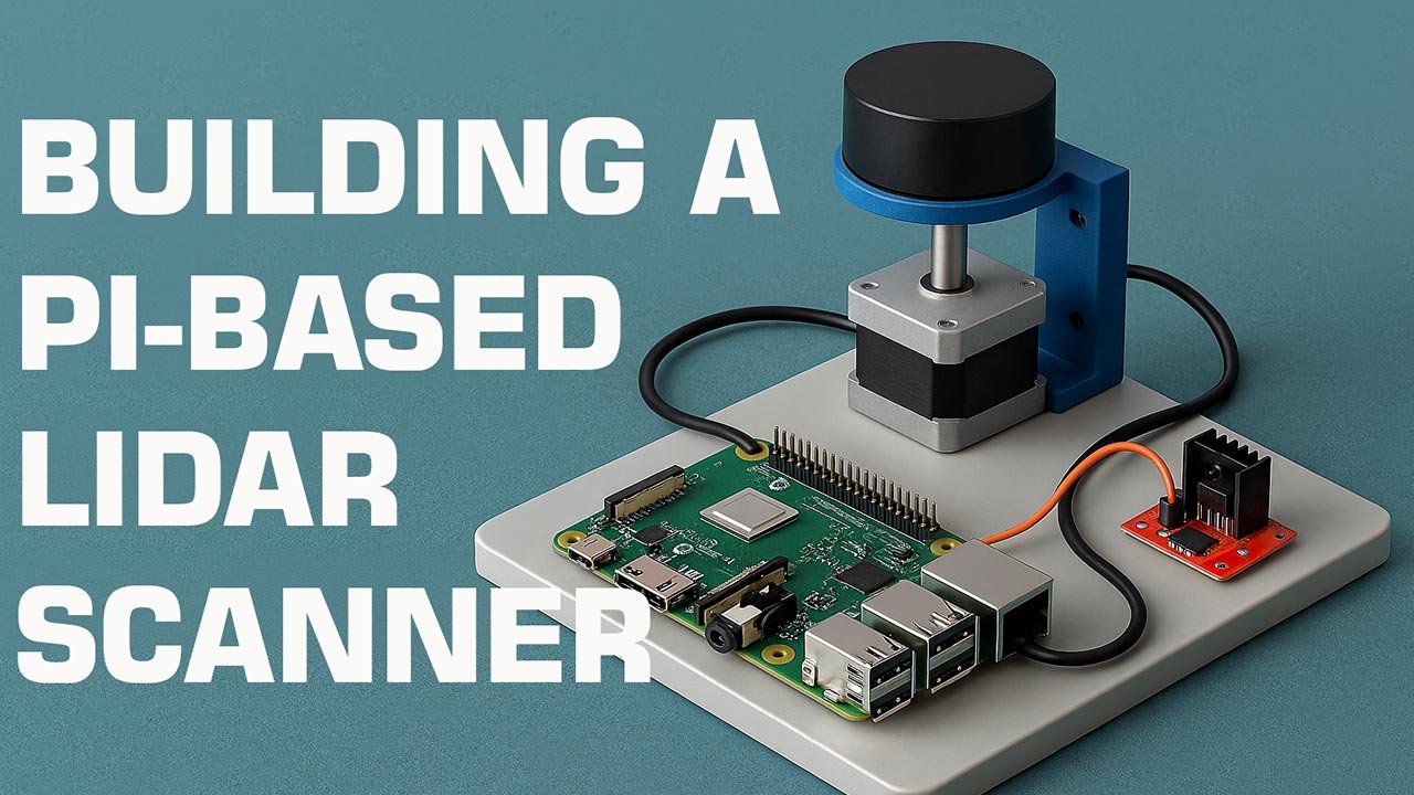
Building a Pi-Based LiDAR Scanner
This article explores how to design, assemble, and optimize a Raspberry Pi–based LiDAR scanner capable of high-resolution 3D mapping. You’ll learn the hardware architecture, software pipeline, calibration workflow, and the innovation principles that make DIY LiDAR systems increasingly viable for robotics, automation, and spatial intelligence applications.
Table of Contents
- Introduction
- Why a Pi-Based LiDAR Scanner?
- Required Hardware Components
- System Architecture Overview
- Building the Scanner
- Software Stack
- Calibration & Optimization
- Applications & Innovation Impact
- Top 5 Frequently Asked Questions
- Final Thoughts
- Resources
Introduction
LiDAR—short for Light Detection and Ranging—has transitioned from a niche scientific tool to a mainstream technology powering robotics, AR/VR environments, autonomous vehicles, warehouse automation, and environmental mapping. Historically, LiDAR systems were cost-prohibitive, bulky, and limited to industrial research. However, modern solid-state sensors, open-source software ecosystems, and single-board computers such as the Raspberry Pi have dramatically lowered the barrier to entry.
This article walks you through the engineering, innovation principles, and practical build steps for creating a Pi-based LiDAR scanner capable of delivering rich point clouds suitable for prototyping and applied research.
Why a Pi-Based LiDAR Scanner?
Cost Efficiency
Commercial LiDAR stations can exceed $5,000–$50,000. Meanwhile, a DIY Raspberry Pi system using an affordable spinning or solid-state sensor often lands in the $100–$350 range.
This democratizes spatial intelligence: students, independent researchers, and hobbyists can create high-value 3D mapping systems without enterprise budgets.
Modularity
The Raspberry Pi supports USB, UART, SPI, and I²C interfaces, making it compatible with almost every consumer-grade LiDAR module. You can upgrade sensors, add inertial measurement units (IMUs), integrate cameras, and more without redesigning the entire device.
Open-Source Ecosystem
Tools such as ROS (Robot Operating System), Python libraries like Open3D, and sensor SDKs allow users to build scalable, customizable workflows. Crucially, the Pi enjoys long-term community support and a rich package ecosystem.
Required Hardware Components
Raspberry Pi Selection
A Pi 4 or Pi 5 is strongly recommended due to:
- Higher CPU throughput for real-time point cloud processing
- USB 3.0 ports for high-bandwidth sensors
- Improved I/O performance for motor control
Although a Pi Zero 2 W works for low-rate scanning, it struggles with high-density data streams.
Compatible LiDAR Sensors
Here are several widely supported LiDAR modules:
| Sensor | Type | Typical Range | Notes |
|---|---|---|---|
| RPLIDAR A1 | Spinning | 12–15m | Budget-friendly, 360° scanning |
| RPLIDAR A2/A3 | Spinning | 25m+ | Higher-resolution mapping |
| YDLIDAR X4/X2L | Spinning | 8–10m | Low-cost, easy setup |
| Benewake TF-Luna / TF-Mini | Solid-state (ToF) | 0.2–12m | Great for directional scanning |
| LD06 LiDAR | Spinning | ~12m | Compact, high sampling rate |
Spinning LiDAR modules yield full 360° coverage, making them ideal for SLAM (Simultaneous Localization and Mapping).
Motor, Mounts & Power
- NEMA 17 stepper motor or high-speed micro motor for rotating sensors lacking built-in spinning assemblies
- Motor driver (A4988 or TB6600 depending on load)
- 12V or 5V power supply, depending on motor specifications
- 3D-printed housing and mounts for structural stabilization
System Architecture Overview
A Pi-based LiDAR scanner follows a consistent data pipeline:
- LiDAR sensor emits laser pulses
- Receiver captures return reflections
- Raw distance and angle data transmitted via USB/UART
- Raspberry Pi parses sensor packets
- Point cloud constructed using timestamp + rotational angle
- Data pushed to ROS topics or visualization tools
- User records scans or processes them for mapping applications
This modular architecture allows developers to add SLAM engines, machine learning models, or onboard filtering algorithms.
Building the Scanner
Mechanical Assembly
- Base Platform:
Use a rigid acrylic or aluminum plate to reduce vibration artifacts. - Sensor Mount:
Attach the LiDAR securely; even minor wobble introduces angular distortion. - Rotary Platform (if using a non-rotating sensor):
- Mount the sensor on a stepper-driven turntable.
- Ensure rotational consistency; speed deviations cause uneven point distribution.
- Vibration Dampening:
Use silicone pads or TPU-printed mounts to reduce motor-induced harmonics.
Electrical Integration
- Connect LiDAR to Pi via USB/UART depending on model.
- Wire the stepper motor driver to GPIO pins:
- STEP, DIR, ENABLE lines from the Pi
- Provide a dedicated power line for motors to avoid Pi brownouts.
- Optionally integrate an IMU (MPU-6050 or BNO055) for motion compensation.
Software Stack
LiDAR Data Acquisition
Depending on the sensor:
- RPLIDAR: Use the
rplidarPython library or ROS packagerplidar_ros. - YDLIDAR: Use their SDK or ROS driver.
- TF-Luna/TF-Mini: Use UART and parse ToF distance frames manually.
Example Python snippet (RPLIDAR):
from rplidar import RPLidar
lidar = RPLidar(‘/dev/ttyUSB0’)
for scan in lidar.iter_scans():
for (_, angle, distance) in scan:
print(angle, distance)
Point Cloud Construction
For 3D point clouds:
- Convert polar → Cartesian coordinates
- Synchronize angle of rotation
- Store (x, y, z) triplets in arrays or PCD files
Example transformation:
import math
x = distance * math.cos(math.radians(angle))
y = distance * math.sin(math.radians(angle))
z = height_offset
3D Visualization
Use Open3D:
import open3d as o3d
pcd = o3d.geometry.PointCloud()
pcd.points = o3d.utility.Vector3dVector(points)
o3d.visualization.draw_geometries([pcd])
You can also stream data directly into RViz via ROS.
Calibration & Optimization
Calibration dramatically increases data accuracy.
Steps:
- Rotational Calibration:
Ensure uniform stepping intervals or use feedback sensors. - Distance Calibration:
Compare LiDAR readings with objects at known distances. - Alignment Calibration:
Misaligned sensors skew point clouds. Use a calibration board (checkerboard patterns) and correct rotation matrices. - Temporal Synchronization:
Timestamp alignment ensures consistent mapping when the system is in motion. - Noise Reduction:
Apply filtering techniques:- Statistical Outlier Removal
- Voxel Downsampling
- Radius-based filtering
Applications & Innovation Impact
Pi-based LiDAR systems open up innovation opportunities:
- Indoor Mapping & 3D Scanning for architectural models
- Autonomous Robotics enabling SLAM and obstacle detection
- AR/VR Spatial Awareness
- Agriculture & Forestry canopy and terrain mapping
- Warehouse Management for object localization and digital twins
Lowering hardware cost expands accessibility, propelling innovation cycles. Rapid prototyping enables researchers to iterate faster, test hypotheses, and integrate LiDAR-based perception into emerging technologies.
Top 5 Frequently Asked Questions
Final Thoughts
The most important takeaway is that LiDAR—once a technology exclusive to industrial giants—is now entirely accessible to innovators at any scale. By combining the Raspberry Pi’s flexibility with open-source software and modular sensors, you can create a fully functional LiDAR scanner that supports research-grade mapping, autonomous navigation, and spatial intelligence applications. The combination of affordability, adaptability, and innovation potential makes the Pi-based LiDAR platform one of the most transformative DIY technologies available today.


Leave A Comment