


Calculating Parallel Resistance: A Complete Guide
Short, fast, and accurate parallel resistance calculations can be the difference between a stable circuit and a costly design failure. This guide unpacks the science, math, and engineering logic behind parallel resistance so you can apply it with confidence in real-world systems.
Table of Contents
- Understanding Parallel Resistance
- Why Parallel Resistance Matters in Modern Circuit Design
- The Core Formula for Calculating Parallel Resistance
- Step-by-Step Calculation Examples
- Common Mistakes Engineers Make
- Industry Applications of Parallel Resistance Calculations
- Top 5 Frequently Asked Questions
- Final Thoughts
- Resources
Understanding Parallel Resistance
Parallel resistance describes the combined electrical resistance of two or more resistors connected across the same two nodes. Unlike series circuits, where resistances add directly, parallel circuits distribute current among multiple paths. This creates a total resistance that is always lower than the lowest single resistance in the group.
Engineers rely on this behavior to increase current capacity, add redundancy, reduce noise, and fine-tune load characteristics. In innovation and technology management, optimizing these resistor configurations helps maintain reliability at scale—from IoT devices to industrial automation systems.
Why Parallel Resistance Matters in Modern Circuit Design
As electronic systems shrink and power efficiency becomes a core design constraint, understanding how current distributes across components is critical. Parallel resistance calculations support:
- Thermal management through current sharing
- Fail-safe design where a single resistor can fail without collapsing the system
- Precision tuning of analog signals and voltage references
- Energy optimization in battery-powered devices
Research shows that incorrect resistance modeling contributes to an estimated 18% of prototype failures in early-stage hardware development. Preventing these failures starts with mastering parallel resistance fundamentals.
The Core Formula for Calculating Parallel Resistance
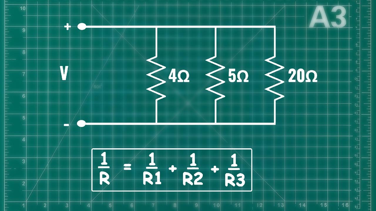
The general formula for n resistors in parallel is:
1/Rtotal = 1/R₁ + 1/R₂ + 1/R₃ + … + 1/Rₙ
Total resistance is the inverse of the sum of the inverses of each resistor.
For two resistors, engineers often use a simplified shortcut:
Rtotal = (R₁ × R₂) / (R₁ + R₂)
This shortcut reduces computation time and improves accuracy when working with paired resistor arrays.
Step-by-Step Calculation Examples
Example 1: Two Resistors
R₁ = 100 Ω
R₂ = 200 Ω
Using the shortcut:
Rtotal = (100 × 200) / (100 + 200)
Rtotal = 20,000 / 300
Rtotal ≈ 66.67 Ω
Example 2: Three Resistors
R₁ = 220 Ω
R₂ = 330 Ω
R₃ = 470 Ω
1/Rtotal = 1/220 + 1/330 + 1/470
1/Rtotal ≈ 0.004545 + 0.003030 + 0.002128
1/Rtotal ≈ 0.009703
Rtotal ≈ 103.06 Ω
Example 3: Mixed High and Low Values
R₁ = 10 Ω
R₂ = 1000 Ω
Because current prefers the lowest resistance path, Rtotal is only slightly lower than 10 Ω.
1/Rtotal = 1/10 + 1/1000
1/Rtotal = 0.1 + 0.001 = 0.101
Rtotal ≈ 9.9 Ω
Common Mistakes Engineers Make
- Assuming resistances add like in series—this leads to dangerously incorrect circuit predictions.
- Rounding too early, which compounds errors in large arrays.
- Ignoring tolerance ratings—a ±5% resistor in parallel can shift load sharing dramatically.
- Not verifying thermal limits—parallel resistors dissipate heat individually but impact total system temperature.
Industry studies indicate that resistance miscalculations contribute significantly to noise, voltage instability, and component overheating in early prototype hardware.
Industry Applications of Parallel Resistance Calculations
Parallel resistance is foundational across industries:
- Consumer Electronics – Smartphone charging circuits use parallel resistance to manage rapid current changes.
- Electric Vehicles – Battery management systems rely on parallel configurations to balance load between cells.
- Telecommunications – RF circuits require precise resistance tuning for signal integrity.
- Industrial Automation – Sensor arrays rely on stable parallel resistance networks for accuracy and safety.
- Innovation & Technology Management – Effective parallel resistance modeling reduces redesign cycles and improves scalability.
Parallel resistance is not just a calculation—it is a strategic design choice that affects performance, lifespan, and innovation velocity.
Top 5 Frequently Asked Questions
Final Thoughts
The most important takeaway is that parallel resistance is about current distribution, not voltage change. Mastering the inverse-sum formula prevents design failures, improves efficiency, and ensures predictable circuit behavior. In modern innovation-driven engineering environments, accuracy in these calculations protects budgets, timelines, and technological reliability.


Leave A Comment