


Breadboard Basics: How to Build Your First Circuit
Learning to use a breadboard is the first major step into hands-on electronics. This guide breaks down internal breadboard connections, power rails, and how to assemble a simple working circuit—so beginners can build confidently and avoid common wiring mistakes.
Table of Contents
- Introduction
- What Is a Breadboard?
- Why Breadboards Matter
- Understanding Internal Breadboard Connections
- Terminal Strips
- Power Rails
- Breaks in the Power Rails
- Tools and Components You Need
- How to Use a Breadboard Step-by-Step
- Step 1: Powering the Board
- Step 2: Adding Components
- Step 3: Understanding Polarity
- Step 4: Testing Your Circuit
- Example Circuit: LED + Resistor
- How It Works
- Why You Need a Resistor
- Common Mistakes Beginners Make
- Top 5 Frequently Asked Questions
- Final Thoughts
- Resources
Introduction
Breadboards are the foundation of rapid prototyping in electronics. Whether you’re building your first LED circuit or experimenting with microcontrollers, understanding how breadboards work ensures your circuits function correctly and safely.
This guide highlights internal breadboard structure—something most beginners overlook—while offering a hands-on example circuit you can build today.
What Is a Breadboard?
A breadboard is a plastic prototyping board filled with internal metal clips that create electrical connections when components are inserted. It allows you to build circuits without soldering, making experimentation fast, clean, and reversible.
Why Breadboards Matter
Breadboards support fast iteration during early-stage hardware design.
They let you test components before committing to a PCB, reduce cost through reuse, and enable fast prototype cycles that reduce failure costs—critical in Innovation and Technology Management where speed and learning matter.
Understanding Internal Breadboard Connections
Correctly understanding the hidden wiring in a breadboard determines whether your circuit works on the first try. The key is knowing what is connected internally and what is not.
Terminal Strips
The terminal strips are the main working areas in the center.
Each row is connected in groups of five holes on each side of the center gap.
The two sides are not connected across the central trench, which is intentional so integrated circuits can straddle the gap without shorting pins together.
Example mental model: a-b-c-d-e are connected in a column of five on the left half, and f-g-h-i-j are connected in a column of five on the right half.
Power Rails
Many breadboards include long side rails intended to distribute power.
These rails are commonly used to run a positive supply line and a ground line so multiple components can share the same power source without messy wiring.
Breaks in the Power Rails
A frequent beginner surprise: power rails are often split near the middle.
That means the top half of a rail is not connected to the bottom half unless you add a jumper wire to bridge the break.
Tools and Components You Need
Breadboard (full or half size)
LED (any standard 3mm or 5mm)
Resistor (typically 220Ω to 330Ω for a 5V source)
Jumper wires
Power source (USB 5V supply, or a battery pack appropriate for your circuit)
Optional but helpful: a multimeter for continuity and voltage checks
How to Use a Breadboard Step-by-Step
A reliable breadboard workflow reduces troubleshooting time and helps you develop strong prototyping habits.
Step 1: Powering the Board
Connect your power source to your distribution points.
If you are using power rails, connect the positive supply to the positive rail and ground to the negative rail.
If your rails are split, add a short jumper wire to connect the two halves you want to behave as one continuous rail.
Step 2: Adding Components
Insert components so each lead lands in a different connected node.
If both leads of a part land in the same 5-hole connected group, the part is effectively bypassed and the circuit won’t behave as expected.
Keep wires as short as practical to reduce clutter and accidental shorts.
Step 3: Understanding Polarity
Some parts must be oriented correctly.
LEDs are polarized: the longer leg is typically the anode (positive) and the shorter leg is the cathode (negative).
Electrolytic capacitors, diodes, and many modules also require correct polarity to work safely.
Step 4: Testing Your Circuit
Before powering on, do a quick sanity check:
Confirm the power source polarity is correct
Confirm the resistor is in series with the LED
Confirm no jumpers accidentally share the same row and short power to ground
If available, use a multimeter continuity test to verify nodes are connected the way you think they are.
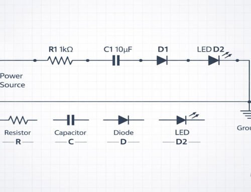
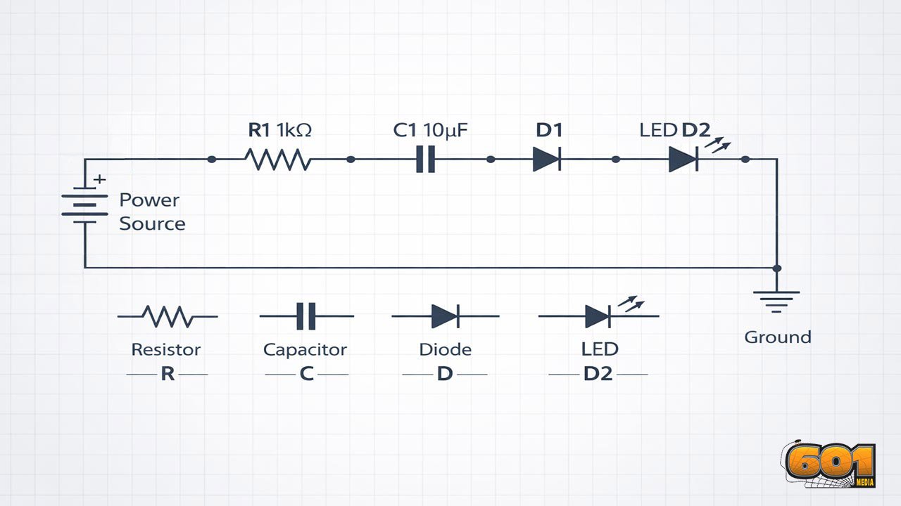
Example Circuit: LED + Resistor
This is the classic first circuit because it teaches current flow, polarity, and current limiting.
The goal is to create a safe current path from the positive supply, through a resistor, through the LED, and back to ground.
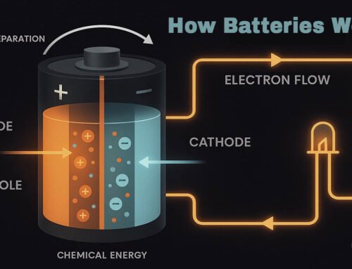
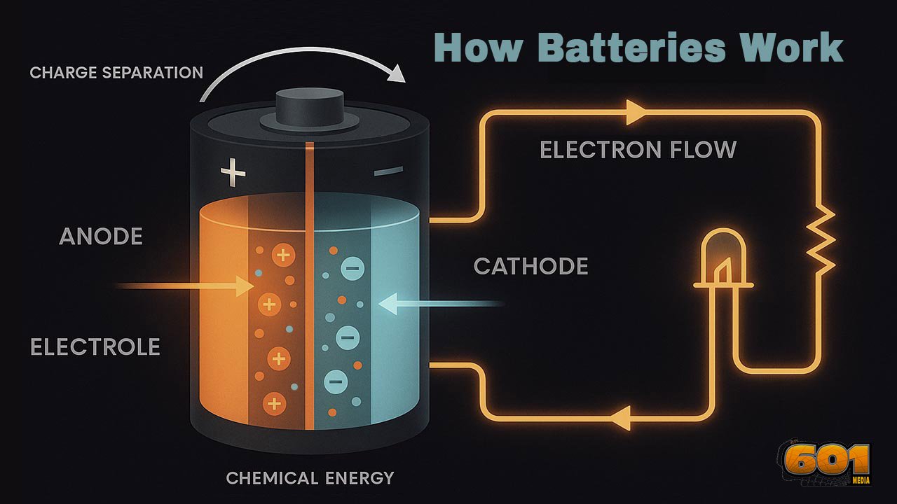
How It Works
When the circuit is complete, current flows from the positive supply into the resistor.
The resistor limits current to a safe level.
The LED then converts some of that electrical energy into light.
The current returns to ground, completing the circuit loop.
Why You Need a Resistor
LEDs are current-driven devices and can be damaged quickly if current is not limited.
A resistor sets the current to a safer range based on supply voltage and the LED’s forward voltage.
Using Ohm’s Law, a common beginner choice for 5V supplies is 220Ω to 330Ω, which typically yields a visible but safe LED brightness.
Common Mistakes Beginners Make
- Plugging both LED legs into the same connected strip
- Forgetting the split in power rails and assuming power is present everywhere
- Reversing LED polarity
- Skipping the resistor and burning out the LED
- Creating an accidental short by placing a jumper into the wrong row
- Assuming the two sides of the center gap are connected
Top 5 Frequently Asked Questions
Final Thoughts
The biggest unlock is mental mapping: terminal strips connect in groups of five, the center gap isolates sides for ICs, and power rails may be split.
When you internalize those rules, breadboarding stops feeling like guesswork and starts feeling like a repeatable engineering method.
From there, you can scale into sensors, microcontrollers, and modular prototypes—exactly the kind of rapid experimentation that accelerates learning and reduces product development risk.


Leave A Comment