


DIY Hobby Maker’s Guide: How Do Electronics Work?
How do electronics work? —voltage, current, and resistance; signals and semiconductors; analog vs. digital; the essential building blocks (resistors, capacitors, diodes, transistors, op-amps, logic gates, and microcontrollers); plus practical design tips so your next breadboard or PCB actually works.
Table of Contents
- The Core Idea: Controlling Energy With Information
- Analog vs. Digital: Two Ways to Think
- The Essential Parts
- Signals, Noise, and Power Integrity
- From Schematic to Reality: Prototyping Tips
- Top 5 Frequently Asked Questions
The Core Idea: Controlling Energy With Information
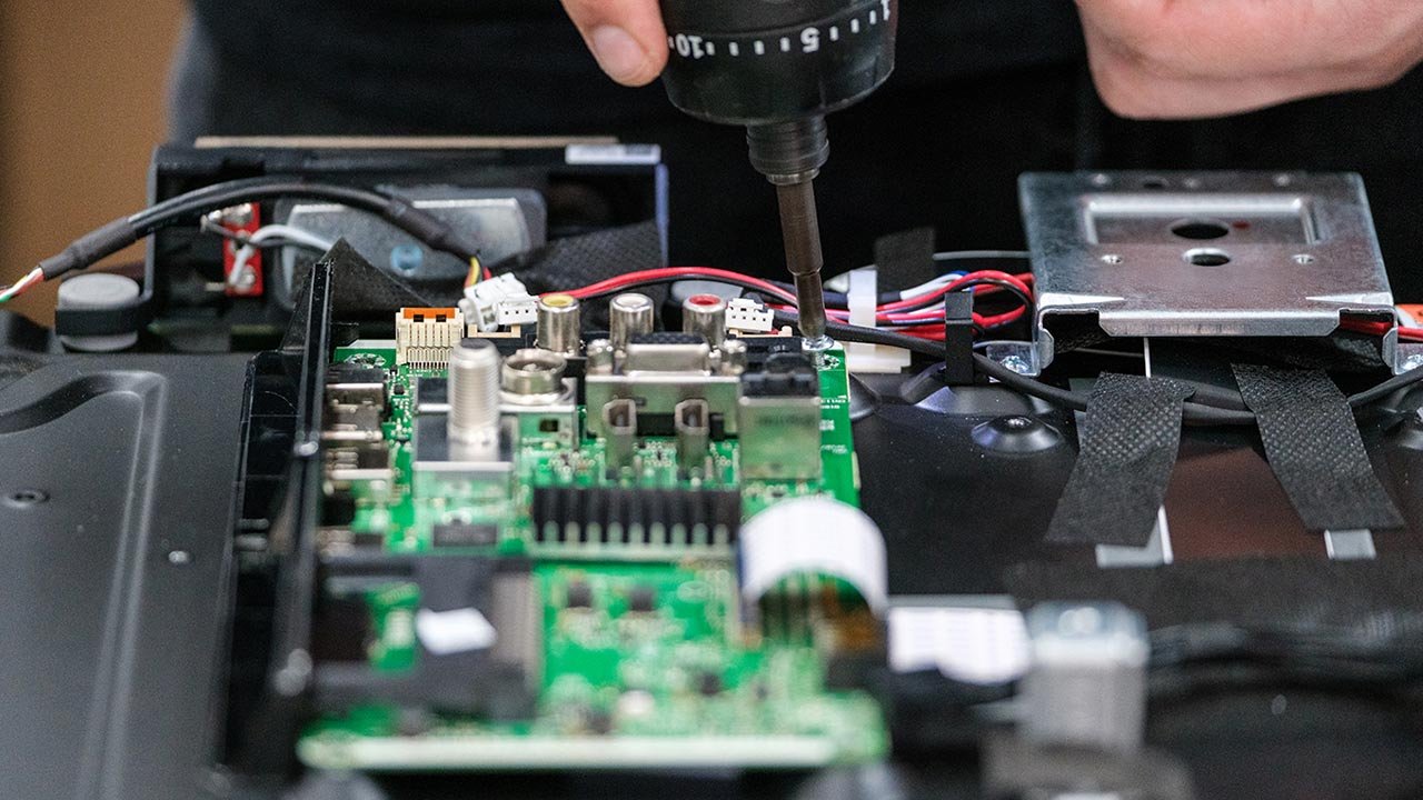
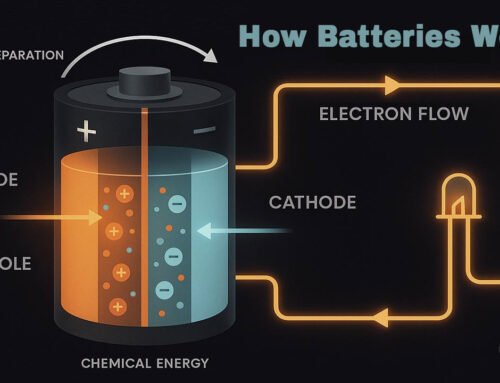
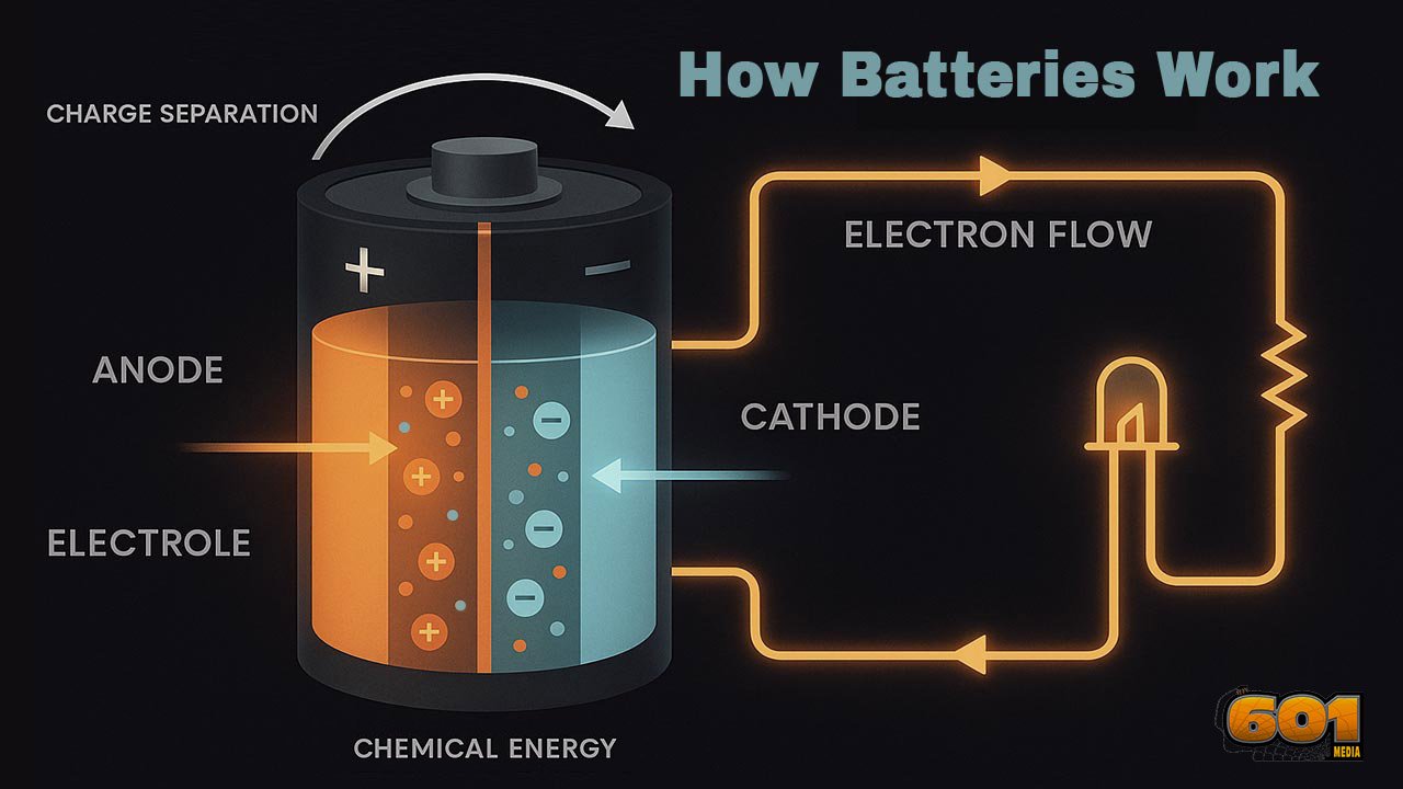
Electronics is the craft of shaping electrical energy so it carries useful information. A microphone turns sound into a tiny varying voltage. Circuits condition that signal—amplify, filter, digitize—so a computer can store or process it. Later, a speaker circuit converts a processed electrical signal back into sound. The through-line is simple: sensors translate the world into electricity; circuits manipulate it; actuators turn it back into the world.
Voltage, Current, and Resistance
- Voltage (V): electrical “pressure,” the energy per charge.
- Current (I): the flow of charge, measured in amperes.
- Resistance (R): opposition to current flow, measured in ohms (Ω).
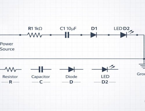
Ohm’s Law, V = I × R, is the maker’s pocket tool. If your LED needs 10 mA at about 2 V and your supply is 5 V, size the series resistor as R ≈ (5 V − 2 V)/0.01 A ≈ 300 Ω. Get comfortable doing these small calculations; they prevent fried parts.
Analog vs. Digital: Two Ways to Think
Analog circuits work with continuously variable signals—audio waveforms, sensor voltages. Precision depends on device tolerances, noise, and layout. Digital circuits encode information as two logic levels (0/1). This makes systems more robust to small errors and lets us build complex behavior from simple building blocks (logic gates, state machines, software).
Most real projects blend both: analog front ends (sensors, filters, amplifiers) feeding ADCs; digital brains (microcontrollers, FPGAs) running code; and analog back ends (DACs, motor drivers, power stages).
The Essential Parts
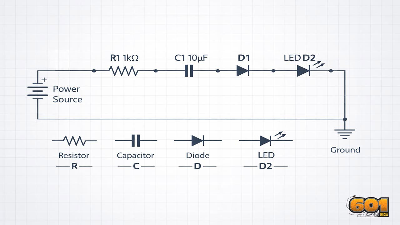
Resistors and Dividers
Resistors set currents, bias transistors, and form voltage dividers. A divider uses two resistors to produce a fraction of a supply—handy for sensing battery voltage. Remember that a divider’s output is fragile: it changes if you load it with a low-impedance circuit. When in doubt, buffer it with an op-amp or choose larger resistor values to reduce current but not so large that noise dominates.
Capacitors and Filtering
Capacitors store and release charge. In power rails, decoupling capacitors (e.g., 0.1 µF ceramic) act like local reservoirs, supplying burst current to ICs and reducing voltage dips. In signal paths, RC networks create filters:
- Low-pass filters remove high-frequency hiss from sensors.
- High-pass filters block DC offset in audio.
- Band-pass can isolate a tone or sensor resonance.
The key parameter is the cutoff frequency, fc=12πRCf_c = \frac{1}{2\pi RC}fc=2πRC1.
Diodes and Rectification
A diode passes current mostly one way. Use them to:
- Protect inputs from reverse polarity.
- Rectify AC to DC in power supplies.
- Clamp transients (e.g., flyback diodes across motors and relays to absorb inductive spikes).
Schottky diodes have lower forward drop, useful when every tenth of a volt matters.
Transistors: The Workhorses
Transistors are controllable valves for current. Two common types:
- BJT (Bipolar Junction Transistor): current-controlled; great for low-cost switches and small amplifiers.
- MOSFET (Metal-Oxide–Semiconductor FET): voltage-controlled; excellent for efficient power switching (motor drivers, LED strips, DC-DC converters).
In switching roles, drive them fully on (saturation for BJTs, appropriate gate voltage for MOSFETs) to minimize heat. In analog roles, set the bias point so the signal swings cleanly without clipping.
Op-Amps: Analog Swiss Army Knives
Operational amplifiers are high-gain differential amplifiers that, with feedback, become whatever you need:
- Voltage follower (buffer) to isolate a divider.
- Non-inverting amplifier to boost sensor outputs.
- Active filters for sharp cutoff without huge capacitors.
- Comparator to detect thresholds (though a real comparator IC is better for fast edges).
Selecting op-amps involves bandwidth, input/output range, noise, and power. For battery gadgets, rail-to-rail I/O and low quiescent current are your friends.
Logic Gates and Microcontrollers
Digital logic gates implement AND, OR, NOT, XOR—the grammar of computation. Combine them into flip-flops (1-bit memory), counters, and state machines. In practice, we often use microcontrollers (AVR, PIC, ARM Cortex-M, ESP32) that bundle CPU, RAM/flash, and peripherals (timers, ADC/DAC, PWM, UART/SPI/I²C, GPIO) on one chip. Firmware translates sensor readings into decisions: debounce a button, average a sensor, modulate a motor, or speak a network protocol.
Signals, Noise, and Power Integrity
Noise rides along with your signal. Sources include thermal noise (resistors), switching noise (digital edges, buck converters), and electromagnetic interference (motors, radios). Mitigations:
- Star grounding and short return paths to avoid ground bounce.
- Bypass capacitors at every IC power pin; place close.
- RC snubbers or flyback diodes for inductive loads.
- Shielded cables and twisted pair for long sensor runs.
- Proper impedance for high-speed traces; keep clocks short and matched.
For power integrity, plan current loops. The loop from source → load → return is an antenna—make it small and tight. Use ground planes on PCBs; route high-current paths wide; separate noisy power stages from sensitive analog areas.
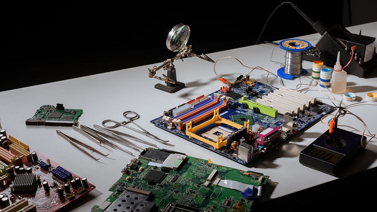
From Schematic to Reality: Prototyping Tips
Start simple. Power the board first; verify rails and grounds before adding ICs.
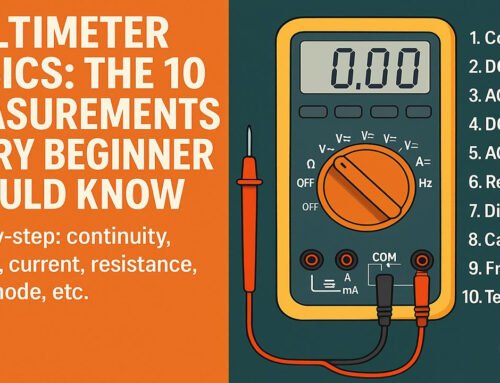
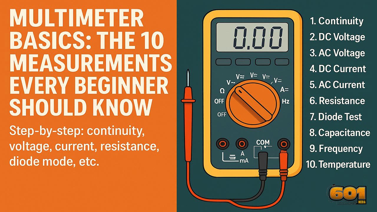
Measure early and often. A basic multimeter and an inexpensive USB oscilloscope unlock insight.
Budget margins. If a regulator delivers 500 mA on paper, plan for 60–70% under continuous load unless you manage heat.
Debounce and filter. Hardware RC networks paired with firmware logic avoid phantom button presses and jittery sensors.
Document values. Label component values and test results in your schematic/README. Future-you will say thanks.
Iterate layouts. Keep decouplers close, trace loops short, and separate analog, digital, and power zones.
Design for failure. Add test points, reset buttons, programming headers, and current-limiting resistors. Use fuses on experimental power rails.
Electronics is about intentional control: pick components that shape energy and information on purpose. Start from the signal: What’s the sensor output? What bandwidth, range, and noise level? Then map the chain: condition (analog) → measure/compute (digital) → actuate (power). Respect power integrity, keep loops tight, and let measurement guide iteration. With that mindset, you’ll turn breadboard chaos into reliable circuits—and your projects will go from “it blinked once” to “it ships.”
Leave A Comment